Dynamic photometry

MIRA

Measuring In-motion Road Analyzer
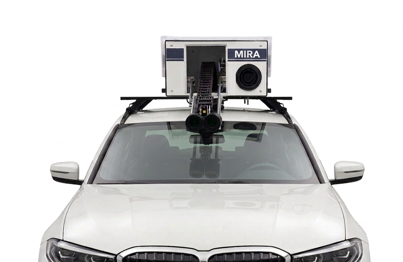
Vehicle equipped as a mobile photometry laboratory with MIRA system.

MIRA is the artificial vision system developed by Sistemi 2 Visione that transforms a vehicle into a mobile photometry laboratory.

It measures the luminance and illuminance of roads and tunnels while traveling at traffic speed and provides a complete characterization of the lighting system: no construction sites, no interruptions, no exposed operators.

  • No construction sites
  • No traffic interruptions
  • Roads and tunnels
  • 5 images/sec of acquisition for each ILMD
  • 5% uncertainty under optimal conditions
  • UNI EN 13201 verification of lighting classes
Vehicle equipped as a mobile photometry laboratory with MIRA system.

Why choose it


The problems MIRA solves

Traditional photometric measurements are slow, expensive, and provide few sample points over a limited area. MIRA eliminates the limitations of the manual method, replacing spot sampling with continuous scanning of the entire road section.

Time and costs out of control

The problem Hours of work to measure just a few kilometers, with specialized personnel, support vehicles, and multiple night trips to complete the campaign.

With MIRA Kilometers of plant measured in a few minutes, with just one vehicle in motion and operating costs optimized by automation.

Operators exposed on the roadway

The problem Spot measurements require personnel on the ground on the road, at night, with all the risks and safety burdens that this entails.

With MIRA No roadside operators: the measurement is taken from inside the vehicle, which moves with the traffic.

Traffic interruption

The problem Lane closures, mobile construction sites, and permits: traditional measurement generates traffic disruption and limits operating hours.

With MIRA High-performance measurements at traffic speeds: no closures, no construction sites, no interruptions to traffic.

Partial and non-representative data

The problem A few isolated points on a sample section do not detect localized faults nor real irregularities along the entire road lighting.

With MIRA Complete scan of every meter of roadway: even anomalies in one or a few lighting fixtures are detected.

Manual processing and errors

The problem Manual transcription and calculations lengthen delivery times and introduce human errors that are difficult to trace retrospectively.

With MIRA Automatic image processing and reporting with color heatmaps, uniformity and glare analysis.

No comparable history

The problem Without georeferenced and historical data, it is impossible to monitor the decay of luminous flux or compare two measurement campaigns.

With MIRA Each measurement is georeferenced via GPS and stored in the system database, ready for energy audits and comparisons over time.

How it works


From vehicle to test report, in three steps

Set up the road lighting

Each road or tunnel lighting is described through an intuitive graphical interface. The data is logged and organized into measurement campaigns and routes.

Measure on the move

The GPS receiver automatically starts measurements near the road lighting. The ILMDs acquire up to 5 images per second at traffic speeds.

Get the report

Automatic processing produces chromatic heatmaps of the luminance on the road surface, uniformity and glare analyses, and lighting class verification.

Strengths


What makes MIRA different

Open an entry to learn more.

Dynamic acquisition

Dynamic road photometric measurements, performed at vehicular traffic speed, in high throughput mode, without construction sites or traffic interruptions.

Road surface luminance measurements for roads and tunnels with verification of uniformity parameters. For tunnels, wall luminance measurements and debilitating luminance measurements in the access area.

Horizontal illuminance measurements, even at road surface level, to verify discrepancies or in areas where luminance is not detectable.

Accuracy

Use of calibrated laboratory instrumentation and sensors, with methodologies compliant with UNI and CEN standards.

Strict compliance with UNI EN 13201 parameters for verifying lighting classes.

Complete mapping

The system doesn't simply acquire samples, but performs a complete scan of every meter of roadway: this allows it to identify even localized problems with one or a few lighting fixtures.

Produce reports with color heatmaps, uniformity and glare analysis.

System Configuration


Different setups, one technology

The mobile laboratory is configured based on the quantities you need to certify and the level of detail required by the test report.

Basic

Measured quantities

  • Road surface luminance
  • Tunnel wall luminance
  • Disturbing luminance in the access area

Output

  • Basic report

Equipment

  • 2 ILMDs for luminance measurement
  • 1 ILMD scene verification

Full

Measured quantities

  • Everything included in Standard
  • Horizontal illumination on street level

Output

  • Multiple measurements report

Equipment

  • 2 ILMDs for luminance measurement
  • 1 ILMD scene verification
  • 2 illuminance measuring cells on street level

Custom

Measured quantities

  • Luminance
  • Illuminance
  • Dimensional measurement
  • Other..

Output

  • Custom report

Custom equipment

  • ILMDs for luminance measurement
  • ILMD scene verification
  • Multiple cells for measuring street level illumination
  • Measuring laser
COMPARE MODELS

Applications and sectors


Who is MIRA designed for?

PUBLIC ADMINISTRATIONS

For the delivery of redevelopment works and verification of street lighting safety requirements.

ESCo & ASSET MANAGERS

For precise energy audits and to monitor the decay of the luminous flux of the systems over time.

DESIGN STUDIES

To validate lighting calculation models with real-world data measured post-installation.

Learn more


Inside the technology

Discover insights into how MIRA acquires, processes, and certifies data.

Acquisition

Data acquisition occurs automatically during mobile laboratory operation.

The system includes several ILMDs (Imaging Luminance Measurement Devices), positioned as required by regulations and configured to maximize resolution and measurable dynamics: in high-throughput mode, operating at traffic speeds, the ILMDs acquire up to 5 images per second each.

Calibration

The system must not only meet regulatory requirements in terms of sensitivity and dynamics, but must also guarantee an uncertainty of 5% under optimal acquisition conditions.

The system includes a section dedicated to calibration, with methodologies and procedures to follow to ensure metrological traceability.

Road lighting management

Each road or tunnel lighting system is described through an intuitive graphic interface: all the data needed for its measurement and subsequent image processing are saved and logged, enriching the database of available systems.

It is also possible to prepare measurement campaigns, organized into specific routes, to facilitate and optimize system measurement.

Execution of measures

Measurement execution is fully automated: thanks to the integrated GPS receiver, measurements begin automatically when approaching the system being assessed.

The operator stays on board the vehicle, which moves with traffic: no construction sites, lane closures, or personnel on the road are required.

Processing measures

The images acquired by the ILMDs are processed automatically, without manual transcription: this reduces delivery times and eliminates errors typical of manual calculations.

The processing produces chromatic heatmaps of luminance on the road surface, uniformity and glare analyses, and lighting class verification. Each measurement is georeferenced via GPS and stored in the system database, allowing for comparison of different campaigns over time.

Test reports

The test report contains more than just numbers, it also provides decision-making tools. It includes:

  • verification of compliance with reference standards;
  • chromatic heatmaps of luminance on the road plan;
  • uniformity and glare analyses.

The Basic and Standard configurations produce the basic report; the Full configuration adds the report with multiple measurements.

Regulations

Measurements are performed with laboratory instruments and calibrated sensors, according to methodologies compliant with UNI and CEN standards.

The main reference is UNI EN 13201, against which the lighting class of the system is verified.

Measured quantities

Depending on the configuration, the mobile laboratory measures:

  • Road surface luminance, for roads and tunnels;
  • Wall luminance in tunnels;
  • Disturbing luminance in tunnel access areas;
  • Horizontal illuminance, for checking for discrepancies and in areas of uncertainty;
  • Horizontal illuminance on road surface (Full configuration only).

The uniformity parameters are checked on all sizes.